
Create/Define Mining Phases
To access this screen:
-
Setup ribbon >> Blocks >> Define Phases.
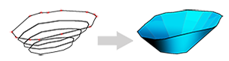
Studio OP uses phase DTMs when you construct mining reserve solids. A phase DTM is an open wireframe surface that represents an individual phase within a pit, for example a pushback or the pit state at a time period.
Use this task to define how many phases your pit contains and how each phase geometry is generated.
You can define phases using one of these methods:
-
Manual – You already have string data that represents each phase. This lets you create and name phases here and then associate each phase with string or DTM data in the Add DTMs task in the managed Reserves Workflow.
-
Use Model – You define phases from strategic planning data in the Define Planning Model.
Phase DTMs are used with pit surface topography to generate Phase Solids. They are also used as a basis for regional slope control, contour generation, road layout experimentation and automated pit design.
3D phase data is generated later as part of a pit design task or a reserves task.
By default, each phase uses the naming convention P#Pit number#_PH#Phase Number#, for example P1_PH2 for the second phase in pit 1. Uncheck Auto to override this naming.
Activity steps:
-
Display the Define DTMs task.
-
Select the Pit you want to define phases for.
-
On the right of the screen, select how you want to define phases:
-
Select Manual to create phases here and define their geometry later using string or DTM data.
-
Select Use Model to define phases from values in the planning model.
-
-
In the Phase Table, define or review the phase list:
-
Use Delete to remove the selected phases.
-
Use Add to add a phase at the end of the list.
-
Use Insert to add a phase below the current selection.
-
Use Up/Down to change the top-to-bottom ordering of the pit.
-
-
To rename a phase, overwrite the existing Name.
-
If you selected Use Model, click Initialize to interrogate the model and populate the Phase Table.
-
This replaces any existing phase information with model-sourced information.
-
Phases are defined from the unique values in the attribute assigned as Optimised phase. If this is not available, Studio OP uses the Mining Phase or LG Phase field assignment in the model.
-
The Model Value column shows the attribute value used for each phase. If you use Manual, this column shows -.
-
-
Continue in the managed workflow, for example use Add DTMs to associate each phase with string or DTM data.
-
Save your project.
Related topics and activities: